

Installation method of ETL (OH5) API 610 on offshore or module mounted application.
This document explains step by step the installation method of an ETL (OH5) pump sole plate on an offshore or module mounted application. Following this procedure guarantees a correct and easy installation. For information on the mounting positions of the bolts, we refer to the GA drawing of the project.
Installation method of ETL (OH5) API 610 on offshore or module mounted application.
Step 1
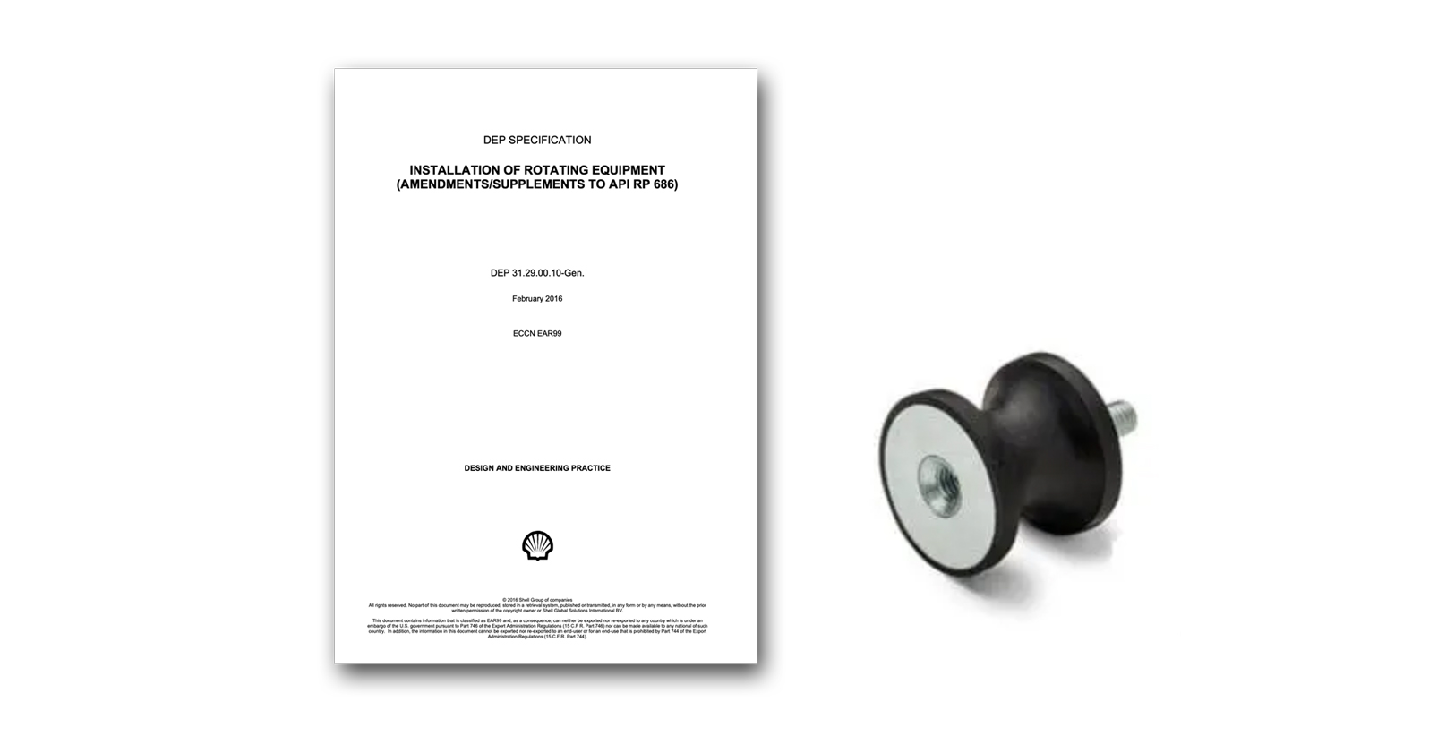
The installation of the ETL (OH5) for offshore or module mounted applications is done in accordance with the philosophy of Shell. As set out in DEP specification 31.29.00.10-Gen. “installation of rotating equipment (amendments/supplements to API RP 686)”.

Step 2
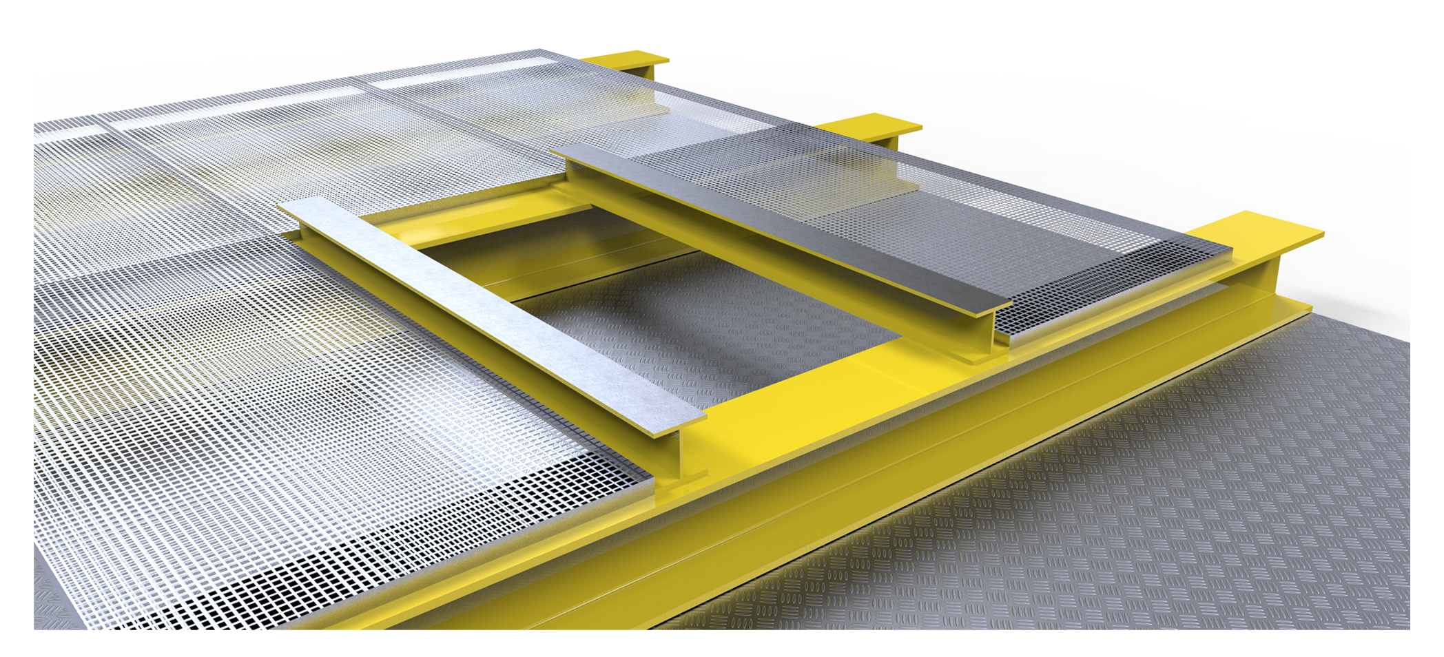
Make sure that the support structure mounting surface is clean, free of grease and paint residues. The support structure must also be flat.( Horizontal)
Step 3
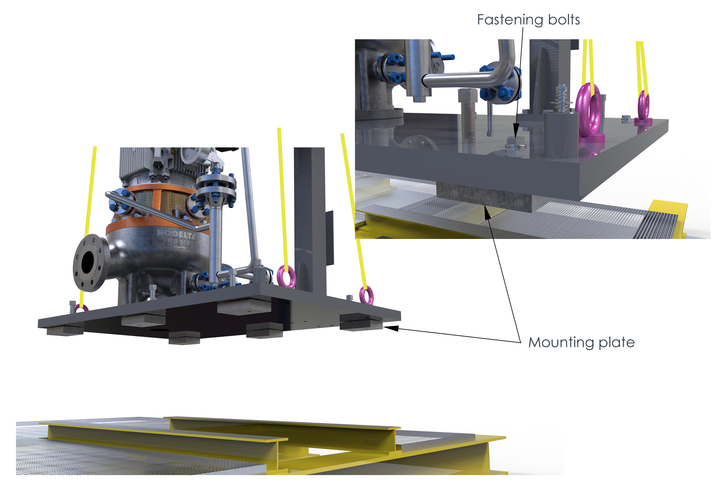
Screw the mounting plate (not in scope Rodelta) to the bottom side of the sole plate with the help of the fastening bolts
Step 4
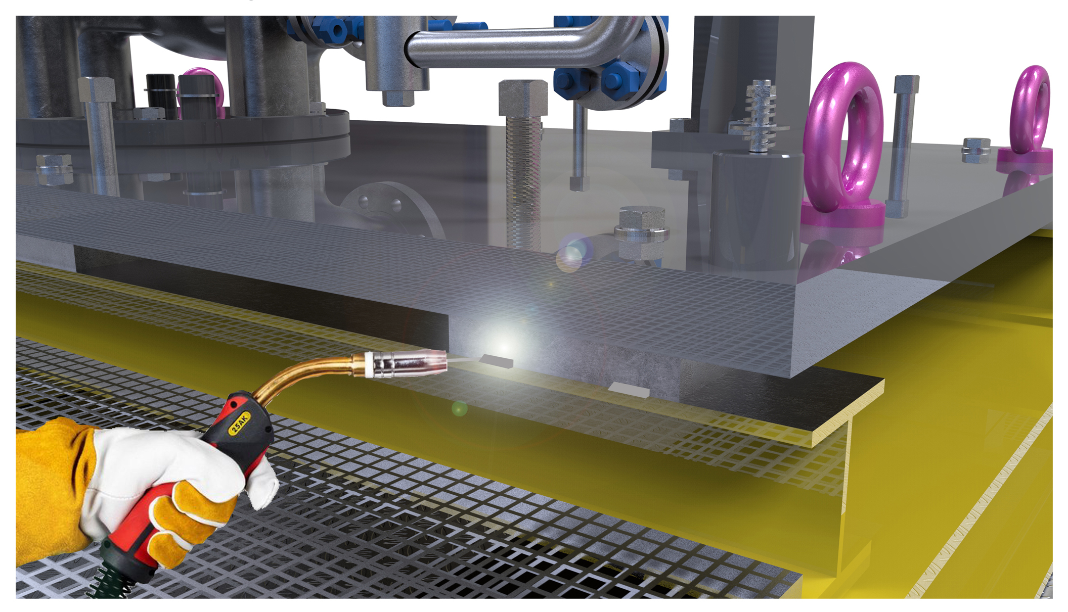
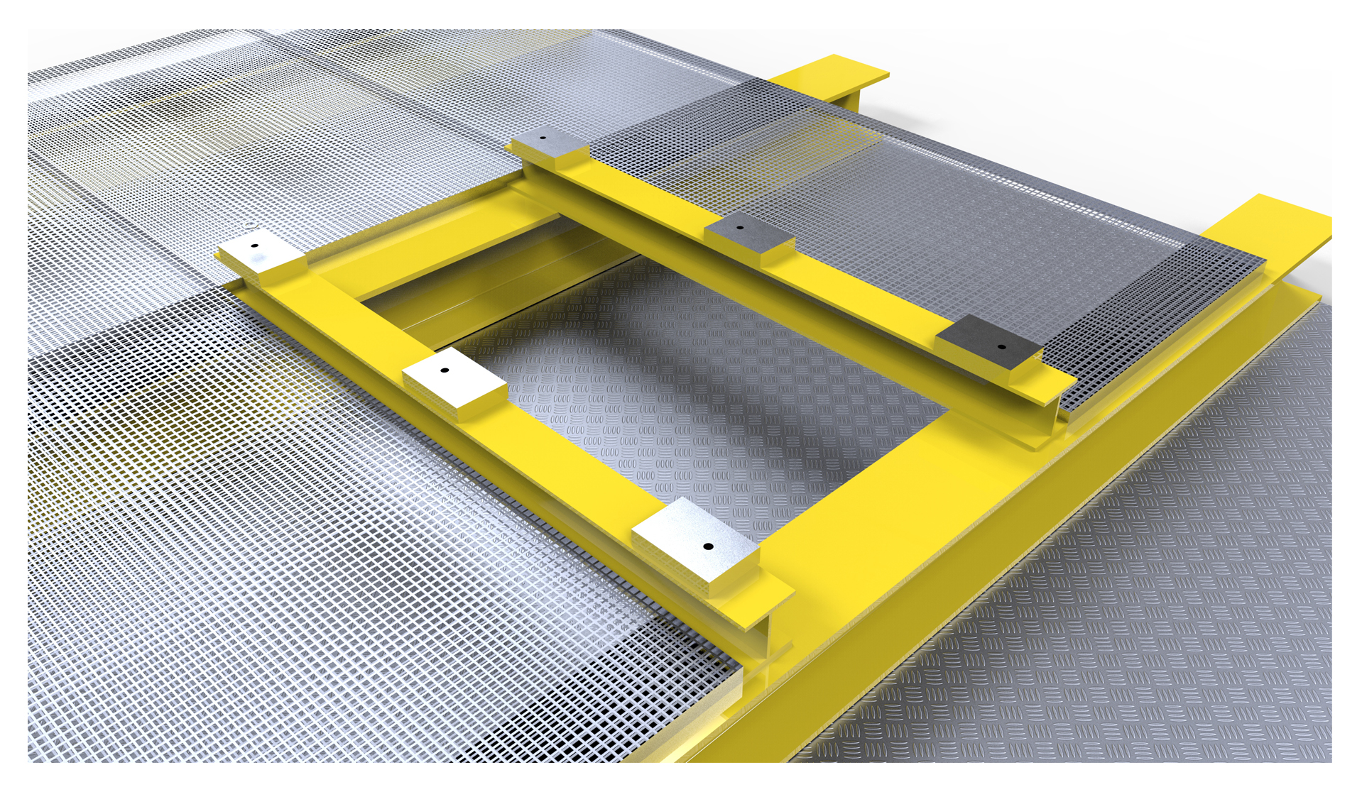
Tack weld the mounting plate to the support structure. Ensure that the mounting plate cannot move when removing the pump with sole plate.
Step 5
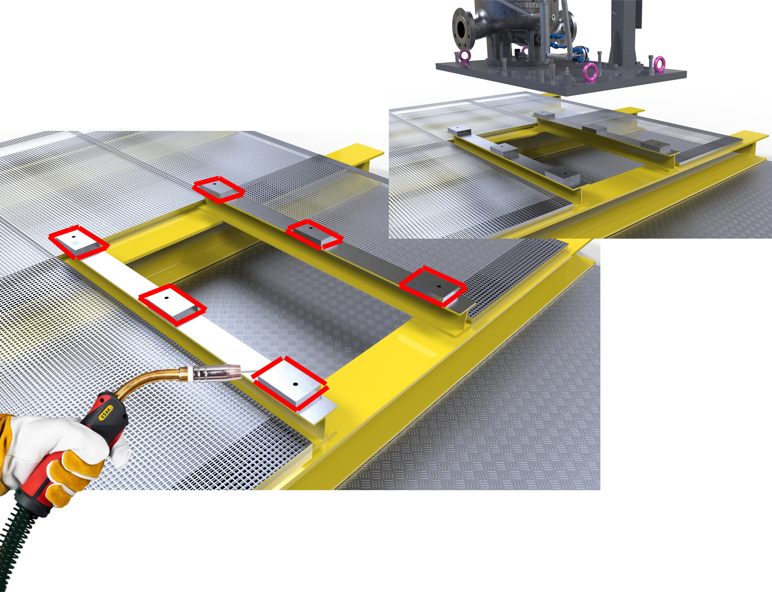
Loosen the fastening bolts and hoist the pump unit with the sole plate from the mounting plates

Step 6
After the pump unit has been lifted off, the mounting plates can be welded all around. This prevents liquid from passing through the non-welded seams and causing corrosion under the mounting plates.
Step 7
Paint all blank parts of the support structure and mounting plates, except for the mounting surfaces.
Step 8
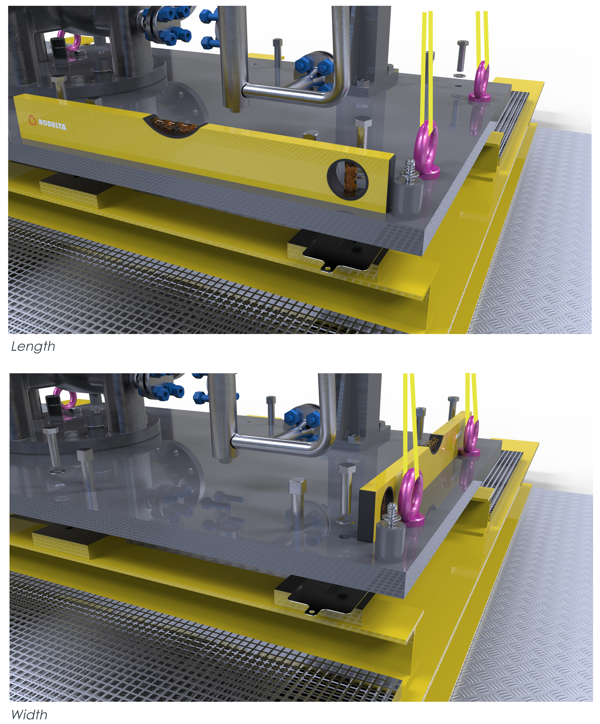
The sole plate with the pump unit can be placed back on the mounting plates. As an option, the pump set can be levelled out with the help of shims. (this can be done if the support structure is not completely horizontal from the beginning) Place the spirit level in the length and width of the sole plate and under fill any unevenness with shims.
Step 9
After the shims have been fitted,(optional) the sole plate can be fixed to the support structure with the bolts.

Step 10
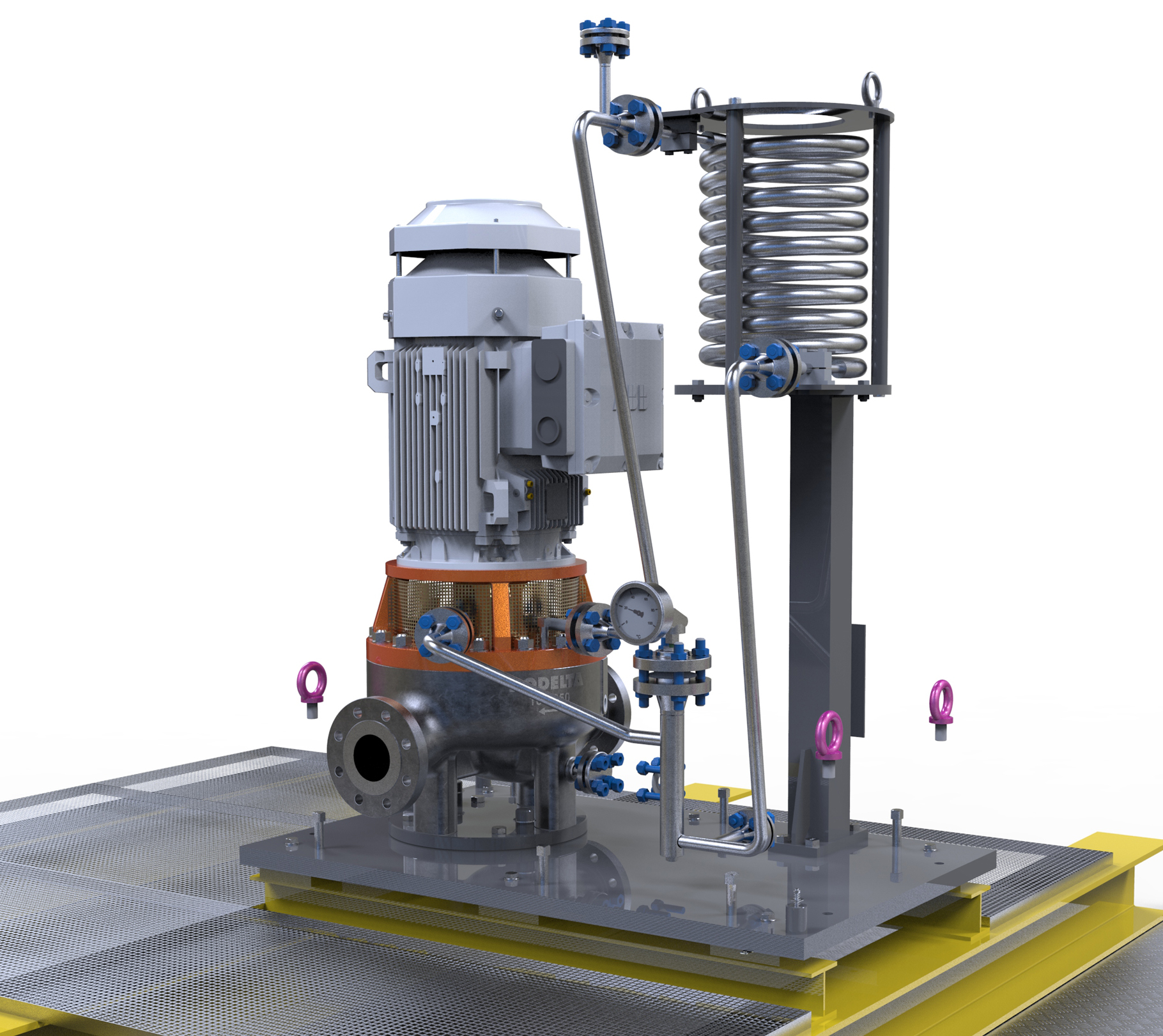
The lifting eyes in the soleplate can be removed. The remaining threaded holes can be closed by screwing in a greased bolt. This prevents any rust from affecting the thread. And it ensures that the threaded holes can also be used for hoisting the pump unit in the future.
Step 11
The installation of the ETL (OH5) API 610 pump is completed. The pipework and electrical cabling can now be fitted.

The DEP 31.29.00.10-Gen also indicates the possibility of using AVM / Gimbal vibration dampers. From a functional point of view this is not necessary for the proper functioning of the Rodelta ETL pump unit. The vibration level of the ETL pump is very low due to its diffuser principle. However, if this is the client’s preference, it can always be supplied and assembled underneath the construction. (Optional)
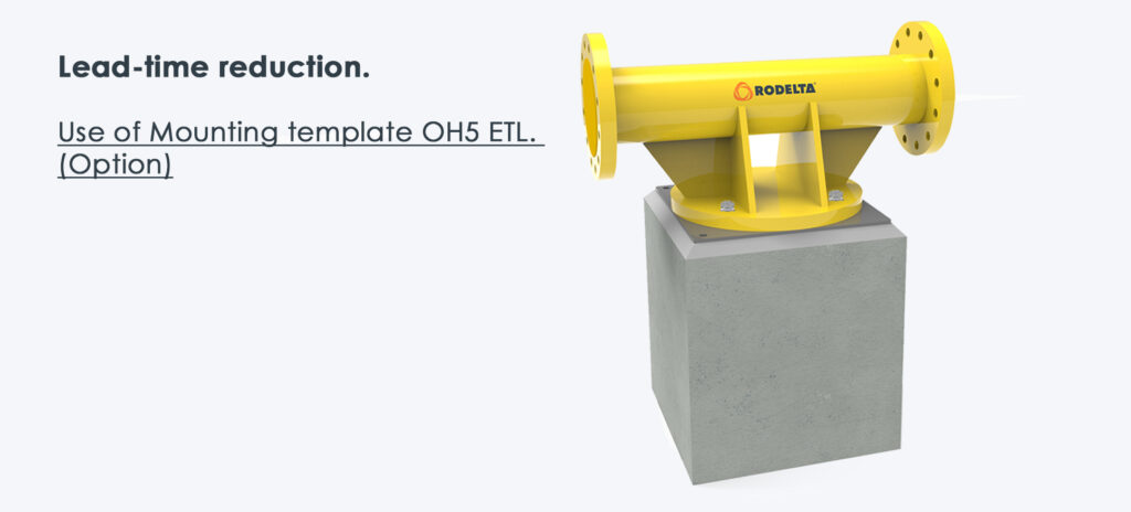
Lead-time reduction.
Use a mounting template OH5 ETL. (Option) A great advantage of the pump type ETL OH5 is, the option of an installation template that allows the start of the installation work of the pump at an early stage. By assembling the sole plate and welding the pipework on site before the actual pump is installed, the overall lead time can be significantly reduced. For more info ETL (OH5) API 610 (Template)
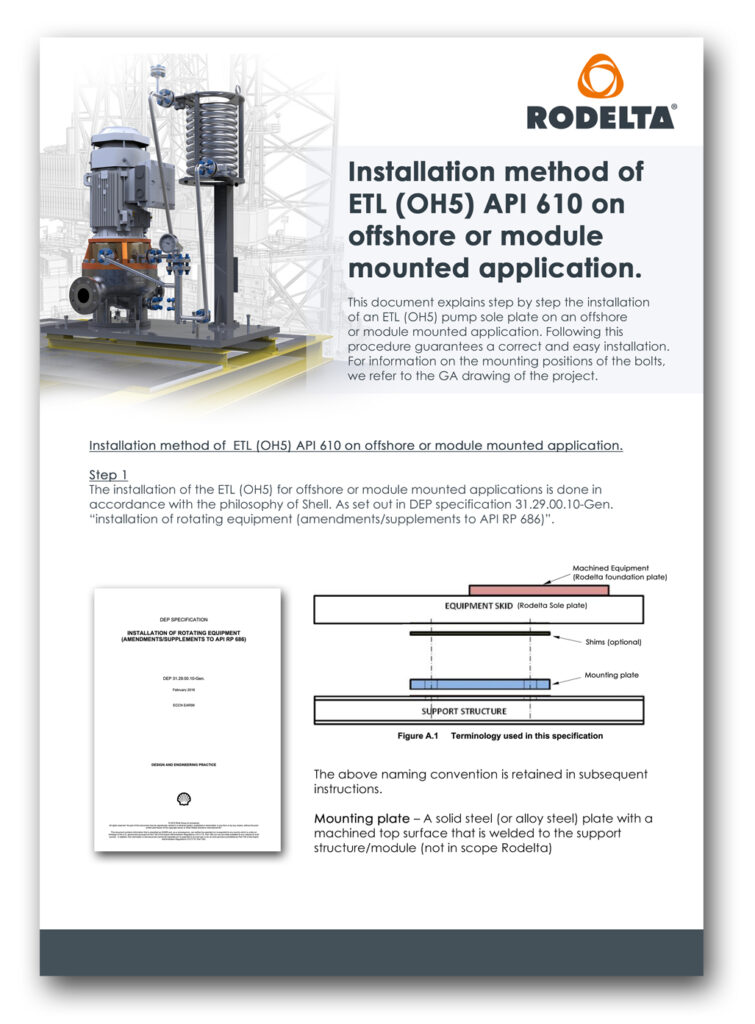
Download brochure installation method of ETL (OH5) API 610 on offshore or module mounted application here.
More information installation ETL (OH5) API 610:
- Installation of a standaard sole plate ETL (OH5) API 610
- Installation of a extended sole plate for ETL (OH5) API 610 pump
- Lead time reduction template ETL (OH5) API 610