

Installation of ETL (OH5) API 610 pump foundation in concrete.

This document explains step by step the installation of a ETL (OH5) pump foundation in concrete. Following this procedure ensure proper and easy installation. For information on the position of the anchor bolts, please refer to the GA of the project. The type of anchor used as well as the depth of the pockets is the customer’s responsibility. This is because selection is highly dependent on the site situation. However, Rodelta can take care of this on request.
Installation of ETL (OH5) API 610 pump foundation in concrete.
Step 1
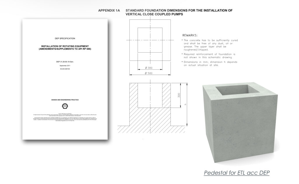
A pedestal for the ETL (OH5) pump can be poured in accordance with dimensions as specified in the DEP. Of course, you as a customer can also choose to apply other dimensions. However, the philosophy of pouring and steps remains the same.
Step 2
The anchors for securing the pump are hanging loosely in the holes of the sole plate. It is absolutely forbidden to tighten them with a nut from the bottom site of the sole plate. (strictly forbidden) This would break the transfer of the forces from the anchor to the concrete. The upper nut / nuts (see picture) from which the anchor hangs in the hole of the sole plate must have the right extension length. This extension length must be the thickness of the foundation plate and the required length of the fastening devices. (Depending on customer anchor choice) Anchor and nuts are not in scope Rodelta but can be supplied as an optional extra.
Also avoid extending the anchors too far so they come into contact with the pump housing.

(Additional clarification info )
The anchor holes in the sole plate are standard 20 mm. By placing anchors with a metric thread of M20 in these holes, the position of the anchor becomes purely centric and straight. This creates space around the holes when placing the foundation plate. This space contributes to a smooth placement and a small adjustability of the pump. (Outer size M20 is always smaller than 20 mm)

Step 3
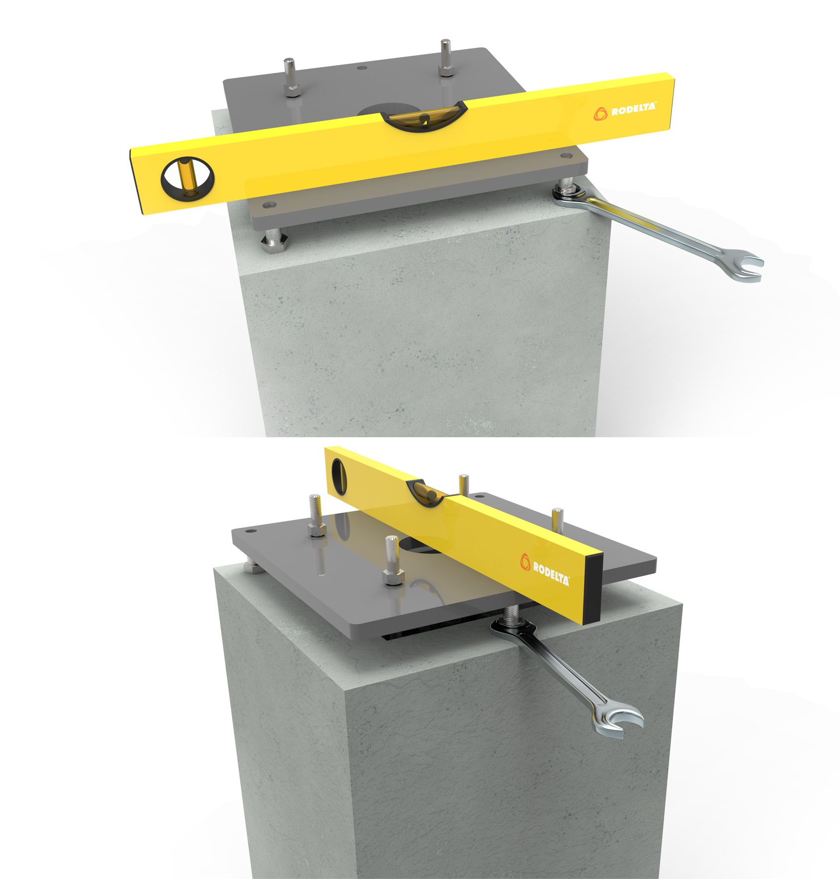
Set the sole plate to the correct height by turning the 3 bolts at the bottom of the sole plate. If the correct height is set, level the sole plate using a plumb rule in horizontal direction.
Step 4
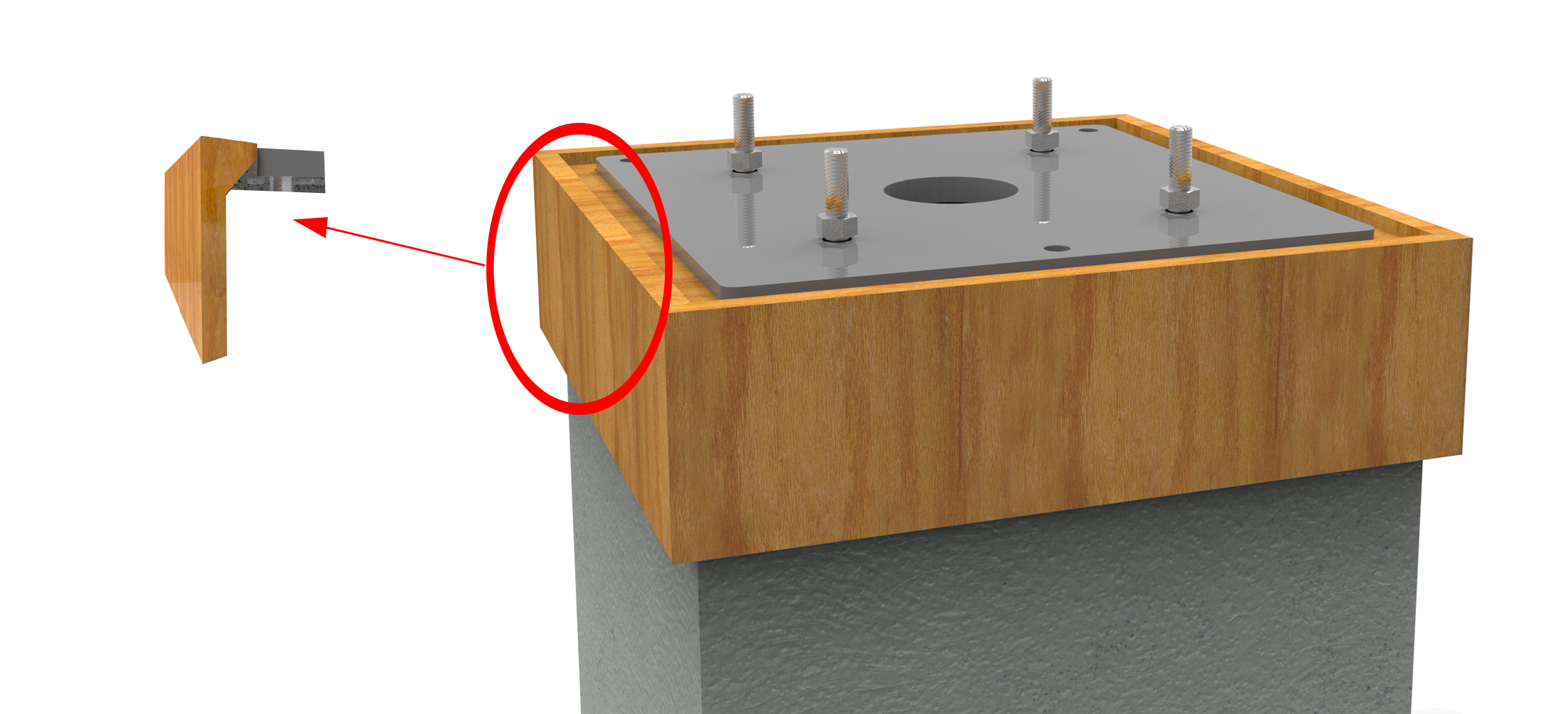
Place formwork for concreting.
A possible chamfer in the formwork can prevent concrete from crumbling. (Tip)
Step 5
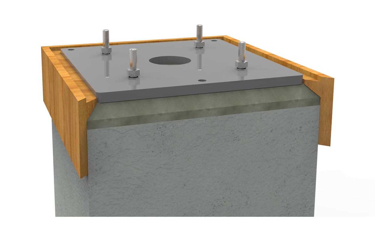
Pour the anchors with shrinkage-free concrete. Make sure that the concrete does not overflow on the top surface. This is the mounting surface for the foundation plate of the pump.

Step 6
After the hardening of the shrinkage-free concrete, the mould can be removed.
Step 7
Unscrew the nuts from the anchors. And clean the top of the sole plate.

Step 8
Place the pump on the sole plate. According the lifting instructions in the Rodelta ETL manual. And tighten the bolts.

Step 9
The pump piping and power cables can be installed. The ETL pump unit does not need to be aligned after assembly. This alignment is in the pump design and has already been checked at Rodelta.

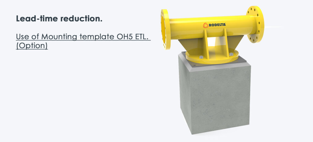
Lead-time reduction.
Use a Mounting template OH5 ETL. (Option)
A great advantage of the pump type ETL OH5. Is the option of an installation template that allows the start of the installation work of the pump at an early stage. By pouring the sole plate and welding the pipework on site before the actual pump is installed, the overall lead time can be significantly reduced. More info here.

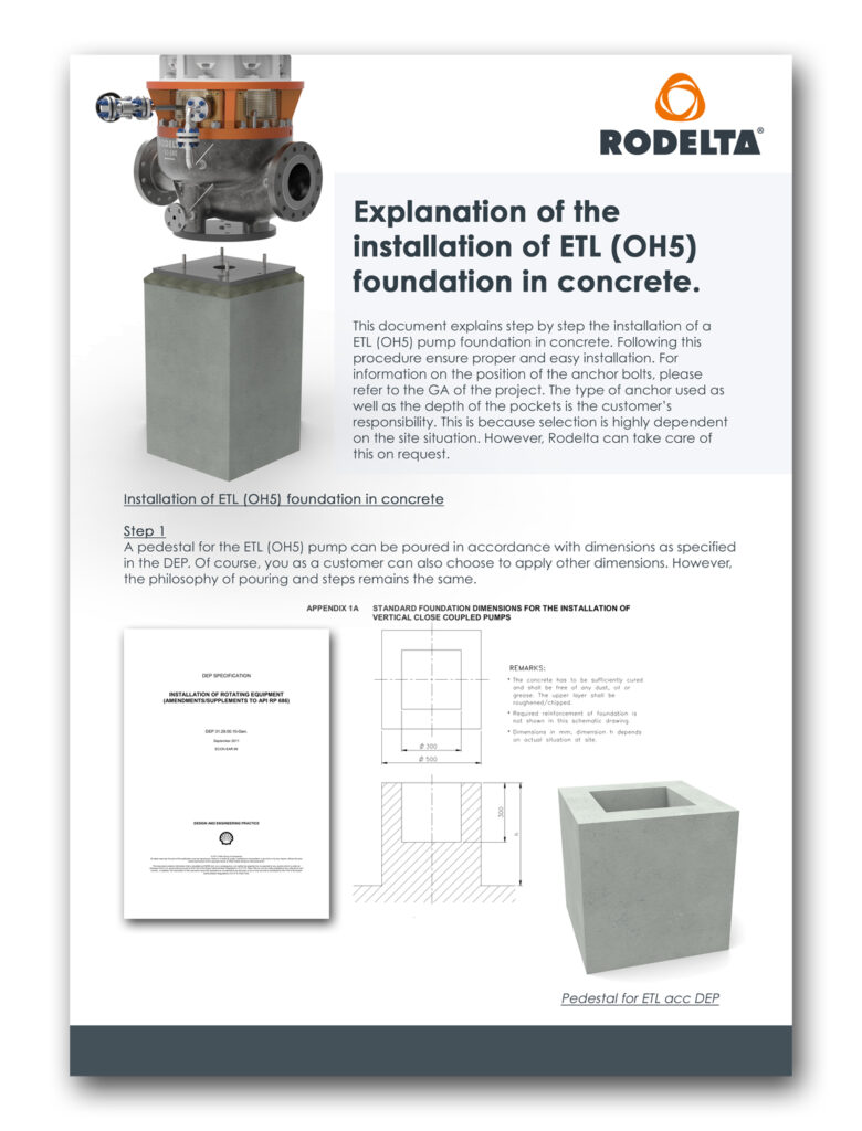
Download brochure installation of ETL (OH5) foundation in concrete here.
More information installation ETL (OH5) API 610: